
A project describes a firmware-fuzzing campaign (see  Definitions for more details). To create a new project, simply follow the next few steps:
1. Upload Your Firmware Binary
Open your web browser and navigate to:
bashhttp://<host>:<port>
You will see the Metalware home screen:
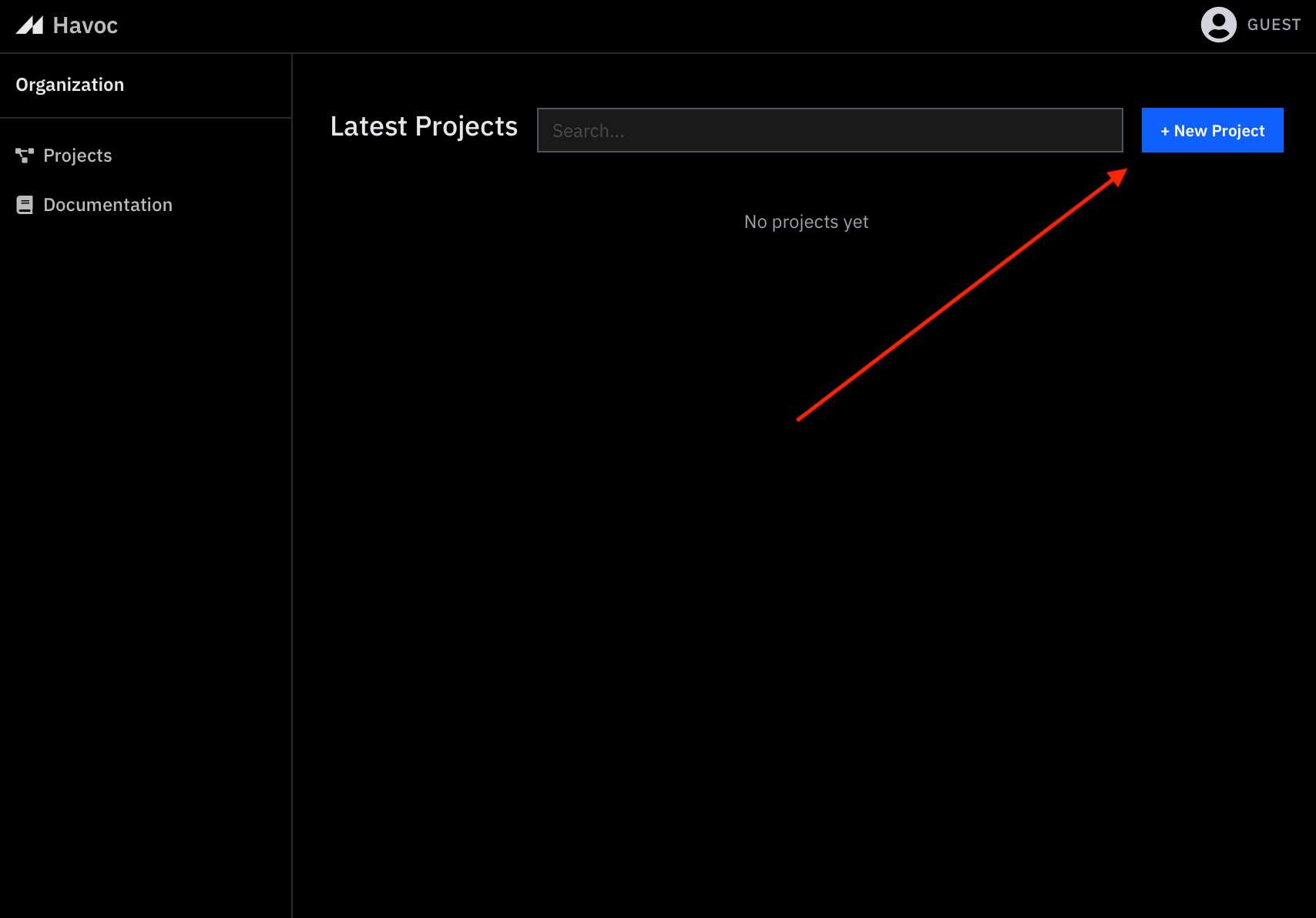
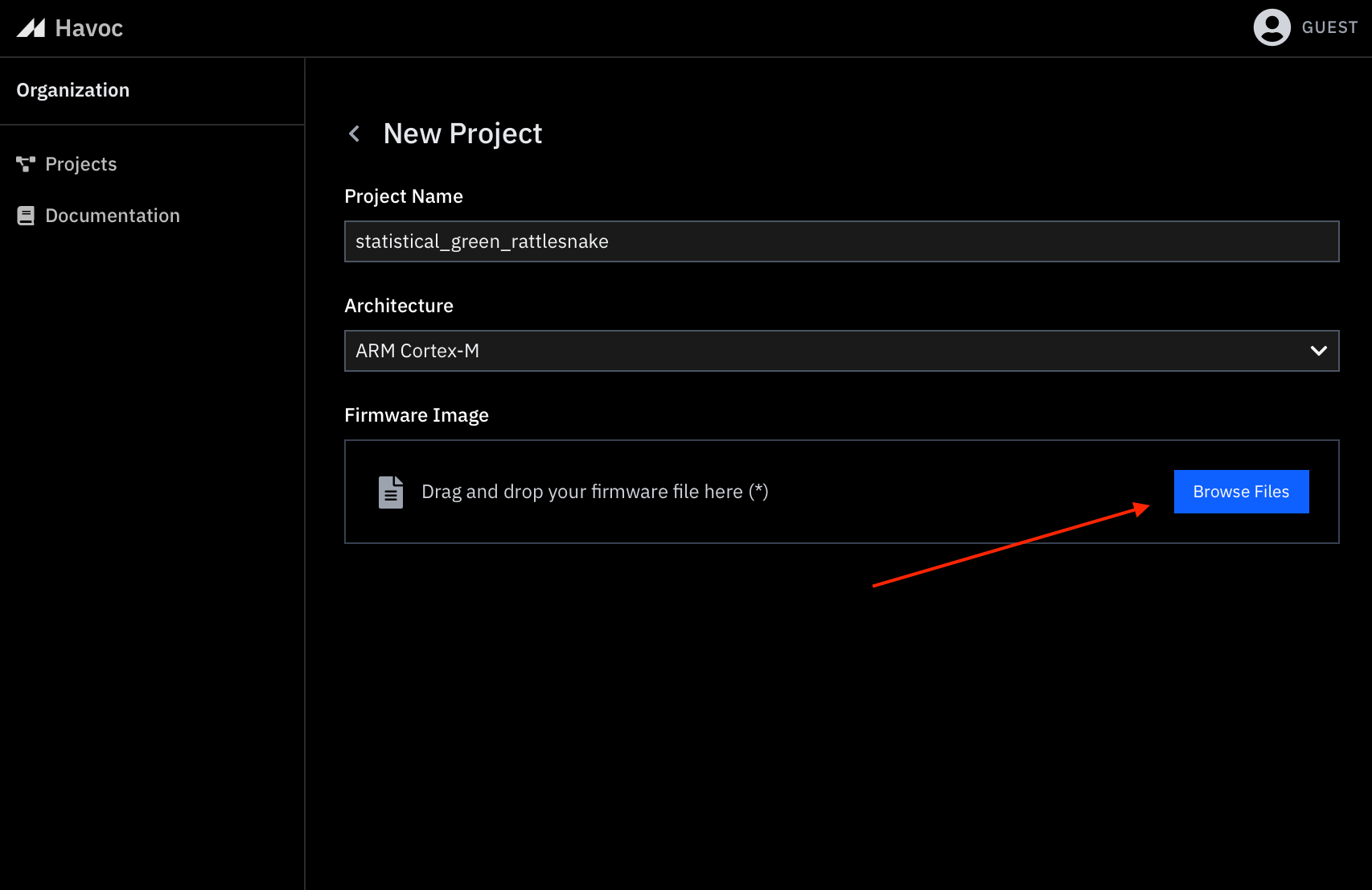
Click the New Project button. This opens a form for uploading your firmware binary. Select an appropriate name and architecture for your project.
See  Supported Targets for the types of targets and image formats we support.
2. Check the Inferred Configuration
Metalware will try to automatically infer an image configuration and a device configuration from the uploaded file:
- Image Configuration
- For an ELF file, Metalware will try to infer the vector table address of the image. A vector table contains the initial stack pointer and exception handlers and is normally found at the start of the text section.
- For a RAW file (.bin), Metalware will try to infer the base address of the firmware file.
- Device Memory Layout
The inferred memory layout should match the one found in the reference manual of the device.
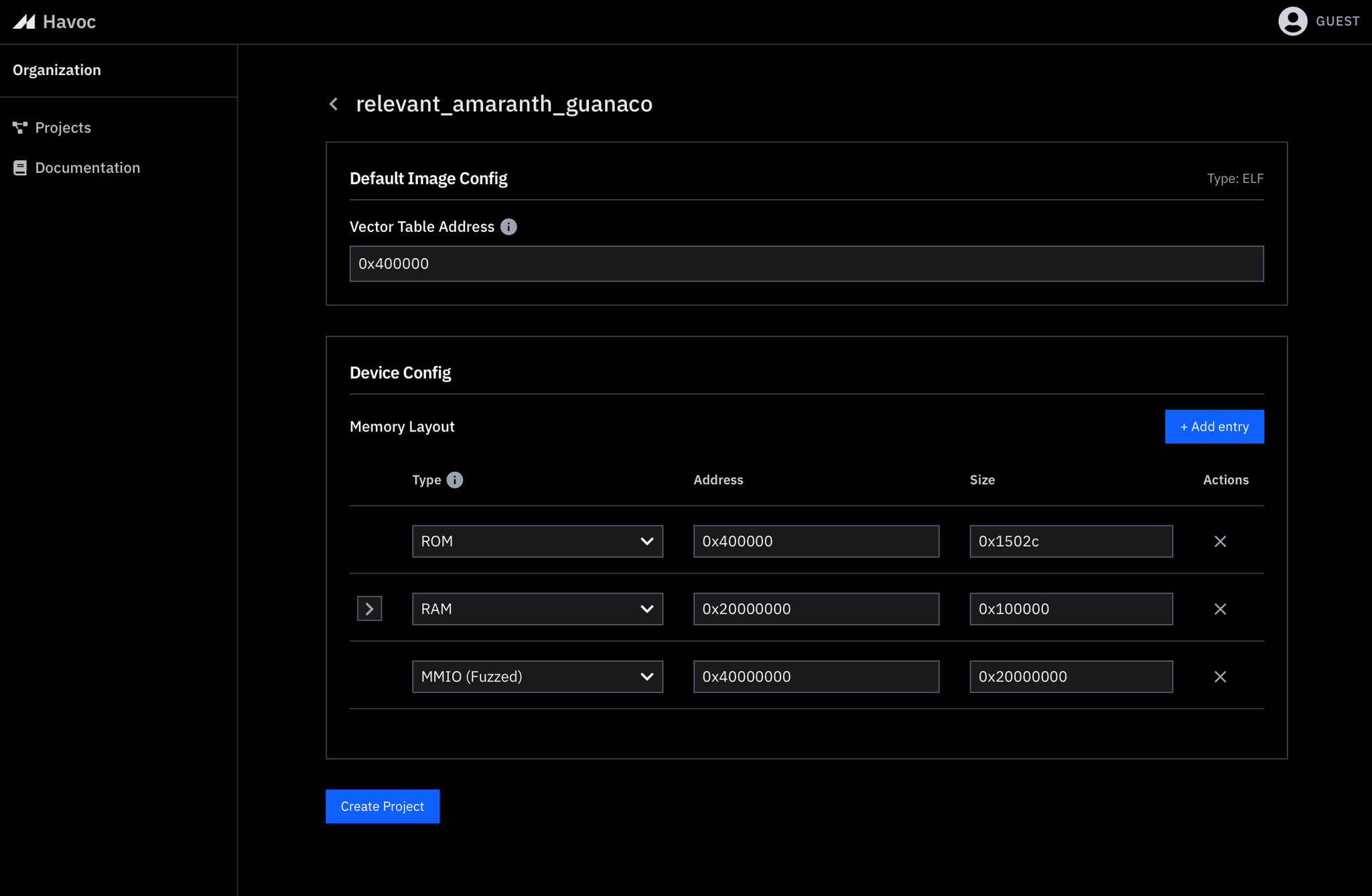
ELF images
An ELF is assumed to contain all code necessary to run the firmware.
If you upload an ELF, you will be presented with the following screen asking you to confirm the inferred device memory layout and vector table address for the image:
RAW images
A RAW image is made up of one or more firmware files.
If you upload a stripped firmware file (.bin), you will be asked to configure it and optionally add additional such files that make up your RAW image:
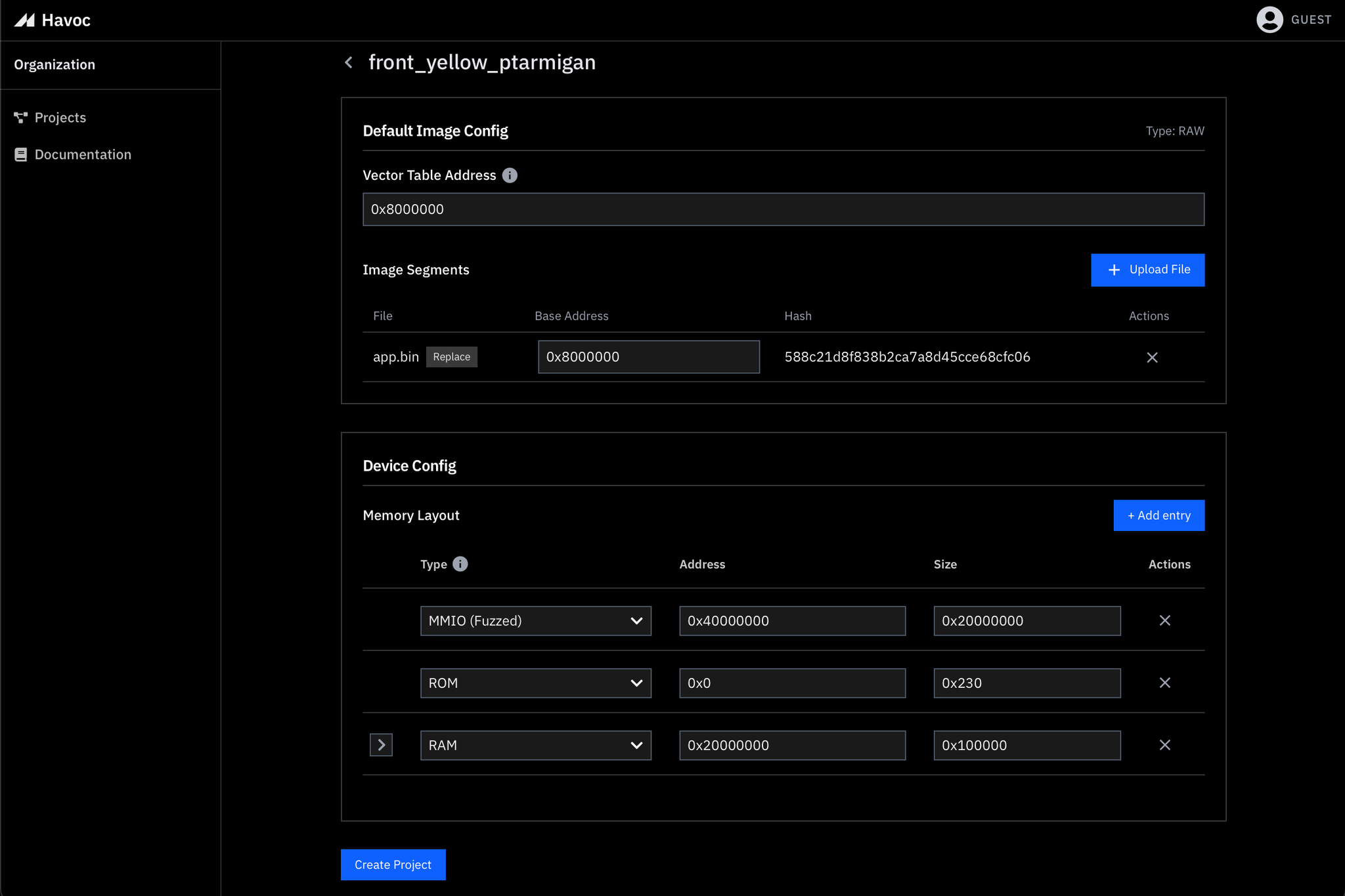
For example, a second file may be necessary for the bootloader, which you can select via
Upload File: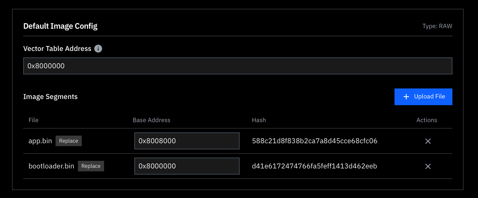
It is sufficient to get the memory configuration correct enough to successfully create the project. When you submit the form, the tool will check the validity of your memory configuration by executing the firmware (we call this a “dry run” of your firmware).
Without knowing everything about the hardware the firmware runs on, it is common to miss memory regions in the initial configuration while still passing the dry run. This is acceptable as any missing memory regions will be caught during fuzzing and can be easily be added to the device configuration later.
Memory Layout Guidelines
Each memory region will fall into one of the following categories:
Memory Type | Data Source | Description |
ROM | Your firmware image. | Flash and ROM-like memory in your SoC’s memory space. |
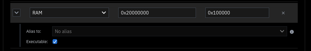
RAM | Initialized to 0. | Volatile memory (e.g., DRAM, SRAM). |
MMIO | Fuzzed. | Memory-mapped I/O for peripherals or secondary memory (e.g., UART, Bluetooth, HSM, Zigbee, external flash). |
If your firmware assumes presence of an External Flash (separate from program flash) with a particular configuration loaded, designate that region as MMIO rather than RAM so that fuzzer will handle any values read from NVRAM.
RAM memory regions can be marked as executable using the toggle.
General Guidelines
- Define small, distinct MMIO regions for board-specific peripherals (i.e. Nordic’s chip id).
- If your firmware interfaces with secondary storage (e.g., external flash, EEPROM, NVRAM) that does not host the firmware image, map that memory region as MMIO.
- For Cortex-M only:
- Allocate a large, contiguous MMIO region for external peripherals (0x40_000_000 is typical). This is automatically inferred for Cortex-M images.
4. Click “Create Project”
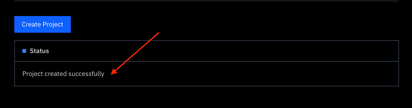
Once you’ve verified the memory maps, click the Create Project button.
Metalware will perform a dry run of your firmware to ensure that the memory map is correctly configured.
✅ Success : If the configuration is correct, you will see a confirmation message in the Status box:
❌ Failure: If there is an error (e.g., a memory segment is too small or missing), you will see an error message similar to the example below:
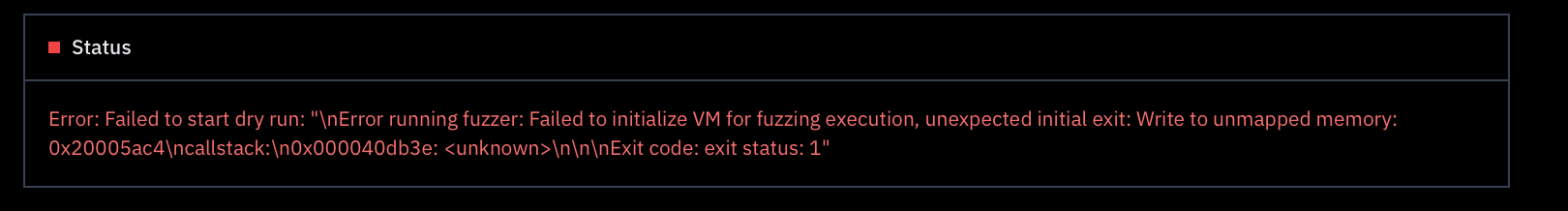
This error above indicates that the RAM region may be undersized:
- We ALREADY have a RAM memory region starting at 0x20000000 of size 0x1000.
- Emulator fails to write to unmapped memory address: 0x20005ac4.
Bumping the size of the region to 0x10000 in this case resolves the issue.